Shipboard power and control cables spend their working life fixed to steelwork in a humid, salt-laden environment, often within reach of cargo, tools and foot traffic. For those runs the IEC 60092 catalogue adds braided armour under the sheath letters, and the armour is coded with two trailing digits: 80, 82, 83, 84 on the copper-braid side and 90, 92, 93, 94 on the steel-braid side. The letters before the digits are decoded in the companion article KEF, CEF, CYJY: Reading Shipboard Cable Codes to IEC 60092; this article is about the numbers.
Where the digits come from
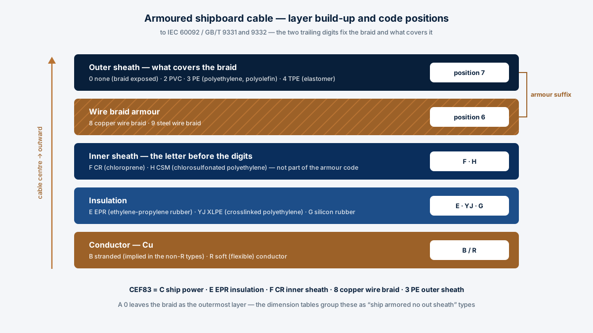
The naming rules assign the sixth position to armour and the seventh to the outer sheath over it. Position six offers two marks: 8 for copper wire braided armour and 9 for steel wire braided armour. Position seven offers four: 0 for no sheath, 2 for PVC (polyvinyl chloride), 3 for PE (polyethylene, polyolefin) and 4 for TPE (elastomer). Read the two digits together and the full armour state of the cable is fixed — which braid, and what covers it.
The armour suffix table
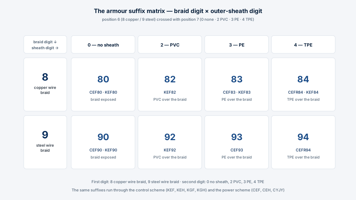
The complete set, with each suffix’s construction and a real designation from the catalogue’s type tables:
| Suffix | Braid (1st digit) | Outer sheath (2nd digit) | Example from the type tables |
|---|---|---|---|
| 80 | Copper wire braid | None | CEF80, CEH80, CYJY80 — ship armoured, no outer-sheath power cable; KEF80 ship control cable |
| 90 | Steel wire braid | None | CEF90 — copper/steel wire braid armoured ship cable; KEF90 ship control cable |
| 82 | Copper wire braid | PVC | KEF82 — EPR insulated CR inner sheathed copper wire braid armoured PVC out sheath ship control cable |
| 92 | Steel wire braid | PVC | KEF92 — steel wire braid armoured PVC out sheath ship control cable |
| 83 | Copper wire braid | PE | CEF83, CEH83, CYJY83 — armoured, PE sheathed ship power cable; KEF83 ship control cable |
| 93 | Steel wire braid | PE | CEF93 — copper/steel wire braid armoured PE sheathed ship cable |
| 84 | Copper wire braid | TPE | CEFR84 — armoured, TPE sheathed ship flexible cable; KEF84 ship control cable |
| 94 | Steel wire braid | TPE | CEFR94 — steel wire braid armoured TPE sheathed ship flexible cable |
One point of reading order matters: in designations such as CEF80 the F is not part of the armour code. The F (or H) is the inner sheath — CR or CSM — applied over the insulated cores before the braid; the catalogue names KEF80 in full as “EPR insulated CR inner sheathed copper wire braid armored ship control cable”. The digits, and only the digits, describe the braid and what covers it.
Copper braid or steel braid?
Both armours in this catalogue are wire braids — 8 a copper wire braid, 9 a steel wire braid — and the type tables list them in pairs: CEF80 with CEF90, CEF83 with CEF93, KEF80 with KEF90. The choice between copper and steel braid, and between bare braid (x0) and a covered one (x2, x3, x4), is made against the installation: where the cable sits, what it can be struck by, and whether the run is fixed or occasionally moved. The catalogue’s using properties frame it plainly — apart from the flexible R types used for soft, indoor mobile requirements, these armoured types are mainly for fixed laying, and the minimum working bending radius follows the scheme: the control family (KEF80 / KEF83) runs on overall diameter — at least 4×D where D≤25 mm and 6×D where D>25 mm — while the power family (CEF / CYJY) sets 4×D unarmoured and 6×D armoured or shielded.
Choosing between no sheath, PVC, PE and TPE
The second digit decides what sits over the braid. A 0 leaves the braid as the outermost layer — the dimension tables group these as “ship armored no out sheath” cables. A 2 extrudes a PVC outer sheath over the braid; a 3 a PE (polyethylene, polyolefin) outer sheath; a 4 a TPE elastomer outer sheath. The covered versions group as “ship armored” proper — CEF83 / CEH83 / CYJY83 are the PE-sheathed power cables, and CEFR84 / CEHR84 / CYJYR84 the TPE-sheathed flexible power cables. Which covering suits a given deck, machinery space or offshore platform is a specification decision the RFQ desk answers against the cable schedule — samples of the standard armoured series are available for evaluation.
Armour across the catalogue
The suffix system covers every shipboard family. In the control scheme, the armoured tables list KEF80 through KEF94 — each of KEF, KEH, KGF and KGH in the 80, 90, 82, 92, 84 and 94 builds. In the power scheme, the CEF family runs CEF80 / CEF90 (no outer sheath), CEF83 / CEF93 (PE sheath) and CEFR84 / CEFR94 (TPE sheath), the CEH family mirrors it with CSM inner sheaths, and the XLPE family adds CYJY80 / CYJY90, CYJY83 / CYJY93 and CYJYR84 / CYJYR94. The power and convert (variable-frequency) tables publish the armoured types at two voltage grades, 0.6/1 kV and 1.8/3 kV, and the flexible armoured versions keep the R before the digits — CEFR80, CYJYR84 — so a mobile drive feed and a fixed run can share one specification line. The full lists sit in the CEF80 / CEF83 armoured power series, the KEF80 / KEF83 armoured control series and the convert / variable-frequency series.
What the armour changes in practice
Two service numbers move when the digits appear. First, the bending radius: an armoured or shielded shipboard cable is laid to at least 6×D, against 4×D for unarmoured — a real constraint in crowded cableways. Second, the mechanical envelope: the braid takes the knocks that would otherwise reach the insulation, which is why the armoured types are the fixed-laying choice on exposed routes. Everything else — the 3.5 × U0 / 5 min withstand test, the −10°C ambient floor, the 85°C conductor limit — is common to the family and is set out in the shipboard code article. A representative armoured construction, from the control tables at 150/250 V:
| Property | KEF80 / KEF83 |
|---|---|
| Construction | EPR insulated, CR inner sheathed, copper wire braid armoured; KEF83 adds a PE outer sheath |
| Voltage grades | 150/250 V and 0.6/1 kV (control); power armour at 0.6/1 kV and 1.8/3 kV |
| Voltage withstand test | 3.5 × U0 for 5 min, without puncture |
| Conductor temperature | Not above 85°C |
| Minimum working bending radius | Control family: ≥4×D (D≤25 mm), ≥6×D (D>25 mm), D = overall diameter; power family (CEF / CYJY): ≥4×D unarmoured, ≥6×D armoured or shielded |
| Laying | Mainly fixed laying; R versions (CEFR80, CYJYR80 etc.) for soft, indoor mobile requirements |
For the marine category as a whole — armoured, shielded and unarmoured — start from Marine & Shipboard Cables; for armoured constructions to other national standards, see Custom by Standard.