Rated voltage
0.6/1kV & 1.8/3kV
Marine & Shipboard Cables
EPR (CEF/CEH) or XLPE (CYJY) insulated shipboard power cables with optional copper braid shield (P) and flexible (R) variants, for power supply of vessels and offshore installations; 1.5–300 mm², 85°C (90°C XLPE).
0.6/1kV & 1.8/3kV
85/90 °C
CEF · CEFP · CEFR · CEFRP · CEH · CEHP +6 more
IEC 60092-353:1995 · GB/T 9331-2008
Structure & Charts
Structure cross-sections and specification charts from the company catalog. Browse with the on-page controls, arrow keys or swipe.
Technical Details
EPR (CEF/CEH) or XLPE (CYJY) insulated shipboard power cables with optional copper braid shield (P) and flexible (R) variants, for power supply of vessels and offshore installations; 1.5–300 mm², 85°C (90°C XLPE).
Flame-retardant per IEC 60332-2000 & GB/T 18380-2001; halogen-free per IEC 60754-1991 & GB/T 17650-1998; low smoke per IEC 61034-1997 & GB/T 17651-1998.
| Core × Section mm² | Conductor Dia. mm | Conductor No. | Insulation TH mm | Shield Tape TH mm | Inner Sheath TH mm | Outer Sheath TH mm | Overall Dia. mm (CEF) | Overall Dia. mm (CEFP) | Weight kg/km (CEF) | Weight kg/km (CEFP) |
|---|---|---|---|---|---|---|---|---|---|---|
| 3×1.5 | 0.52 | 7 | 0.7 | 0.1 | 1.0 | 0.8 | 8.4 | 10.3 | 115 | 182 |
| 3×2.5 | 0.67 | 7 | 0.7 | 0.1 | 1.1 | 0.8 | 9.6 | 11.5 | 162 | 238 |
| 3×4.0 | 0.84 | 7 | 0.7 | 0.1 | 1.1 | 0.9 | 10.7 | 12.8 | 220 | 310 |
| 3×6.0 | 1.03 | 7 | 0.7 | 0.1 | 1.2 | 0.9 | 12.1 | 14.2 | 302 | 403 |
| 3×10 | 1.38 | 7 | 0.7 | 0.1 | 1.2 | 0.9 | 13.4 | 15.5 | 431 | 543 |
| 3×16 | 1.74 | 7 | 0.7 | 0.1 | 1.3 | 1.0 | 15.7 | 18.0 | 641 | 780 |
| 3×25 | 2.19 | 7 | 0.9 | 0.1 | 1.4 | 1.1 | 19.4 | 21.9 | 993 | 1173 |
| 3×35 | 2.58 | 7 | 0.9 | 0.1 | 1.5 | 1.1 | 21.9 | 24.4 | 1328 | 1530 |
| 3×50 | 2.52 | 10 | 1.0 | 0.1 | 1.7 | 1.2 | 25.1 | 27.8 | 1781 | 2027 |
| 3×70 | 2.55 | 14 | 1.1 | 0.1 | 1.8 | 1.3 | 29.3 | 32.2 | 2505 | 2806 |
| 3×95 | 2.58 | 19 | 1.1 | 0.1 | 1.9 | 1.4 | 33.2 | 36.3 | 3379 | 3738 |
| 3×120 | 2.57 | 24 | 1.2 | 0.1 | 2.1 | 1.5 | 37.0 | 40.3 | 4221 | 4639 |
| 3×150 | 2.56 | 30 | 1.4 | 0.1 | 2.2 | 1.6 | 41.2 | 44.7 | 5234 | 5721 |
| 3×185 | 2.58 | 37 | 1.6 | 0.1 | 2.4 | 1.7 | 46.1 | 49.8 | 6547 | 7116 |
| 3×240 | 2.57 | 49 | 1.7 | 0.1 | 2.6 | 1.9 | 52.0 | 56.1 | 8502 | 9197 |
| 3×300 | 2.58 | 61 | 1.8 | 0.1 | 2.8 | 2.0 | 57.5 | 61.8 | 10578 | 11377 |
| Core × Section mm² | Conductor Dia. mm | Conductor No. | Insulation TH mm | Shield Tape TH mm | Inner Sheath TH mm | Outer Sheath TH mm | Overall Dia. mm (CEF) | Overall Dia. mm (CEFP) | Weight kg/km (CEF) | Weight kg/km (CEFP) |
|---|---|---|---|---|---|---|---|---|---|---|
| 3×1.5 | 0.52 | 7 | 0.7 | 0.2 | 1.0 | 0.8 | 8.4 | 10.8 | 115 | 186 |
| 3×2.5 | 0.67 | 7 | 0.7 | 0.2 | 1.1 | 0.8 | 9.6 | 12.0 | 162 | 242 |
| 3×4.0 | 0.84 | 7 | 0.7 | 0.2 | 1.1 | 0.9 | 10.7 | 13.3 | 220 | 315 |
| 3×6.0 | 1.03 | 7 | 0.7 | 0.2 | 1.2 | 0.9 | 12.1 | 14.7 | 302 | 408 |
| 3×10 | 0.25 | 184 | 0.7 | 0.2 | 1.2 | 0.9 | 14.1 | 16.7 | 430 | 552 |
| 3×16 | 0.30 | 204 | 0.7 | 0.2 | 1.3 | 1.0 | 16.6 | 19.4 | 640 | 793 |
| 3×25 | 0.30 | 315 | 0.9 | 0.2 | 1.4 | 1.1 | 20.3 | 23.3 | 968 | 1165 |
| 3×35 | 0.30 | 441 | 0.9 | 0.2 | 1.5 | 1.1 | 23.1 | 26.1 | 1304 | 1527 |
| 3×50 | 0.30 | 630 | 1.0 | 0.2 | 1.7 | 1.2 | 26.9 | 30.1 | 1826 | 2098 |
| 3×70 | 0.30 | 896 | 1.1 | 0.2 | 1.8 | 1.3 | 31.2 | 34.6 | 2532 | 2864 |
| 3×95 | 0.30 | 1197 | 1.1 | 0.2 | 1.9 | 1.4 | 35.1 | 38.7 | 3299 | 3691 |
| 3×120 | 0.30 | 1520 | 1.2 | 0.2 | 2.1 | 1.5 | 39.4 | 43.2 | 4171 | 4629 |
| 3×150 | 0.30 | 1900 | 1.4 | 0.2 | 2.2 | 1.6 | 43.9 | 47.9 | 5197 | 5730 |
| 3×185 | 0.30 | 2325 | 1.6 | 0.2 | 2.4 | 1.7 | 48.6 | 52.8 | 6367 | 6983 |
| 3×240 | 0.30 | 3040 | 1.7 | 0.2 | 2.6 | 1.9 | 54.9 | 59.5 | 8226 | 8977 |
| 3×300 | 0.30 | 3800 | 1.8 | 0.2 | 2.8 | 2.0 | 60.7 | 65.5 | 10192 | 11054 |
| Core × Section mm² | Conductor Dia. mm | Conductor No. | Insulation TH mm | Shield Tape TH mm | Inner Sheath TH mm | Outer Sheath TH mm | Overall Dia. mm (CEFR) | Overall Dia. mm (CEFRP) | Weight kg/km (CEFR) | Weight kg/km (CEFRP) |
|---|---|---|---|---|---|---|---|---|---|---|
| 3×1.5 | 0.52 | 7 | 1.0 | 0.2 | 1.1 | 0.8 | 9.9 | 12.3 | 146 | 216 |
| 3×2.5 | 0.67 | 7 | 1.0 | 0.2 | 1.1 | 0.9 | 10.9 | 13.5 | 190 | 272 |
| 3×4.0 | 0.84 | 7 | 1.0 | 0.2 | 1.2 | 0.9 | 12.2 | 14.8 | 257 | 348 |
| 3×6.0 | 1.03 | 7 | 1.0 | 0.2 | 1.2 | 0.9 | 13.4 | 16.0 | 337 | 437 |
| 3×10 | 0.25 | 184 | 1.0 | 0.2 | 1.3 | 1.0 | 15.6 | 18.4 | 478 | 600 |
| 3×16 | 0.30 | 204 | 1.0 | 0.2 | 1.4 | 1.0 | 18.1 | 20.9 | 696 | 837 |
| 3×25 | 0.30 | 315 | 1.2 | 0.2 | 1.5 | 1.1 | 21.8 | 24.8 | 1036 | 1213 |
| 3×35 | 0.30 | 441 | 1.2 | 0.2 | 1.6 | 1.2 | 24.6 | 27.8 | 1381 | 1590 |
| 3×50 | 0.30 | 630 | 1.4 | 0.2 | 1.7 | 1.3 | 28.7 | 32.1 | 1926 | 2181 |
| 3×70 | 0.30 | 896 | 1.4 | 0.2 | 1.9 | 1.4 | 32.7 | 36.3 | 2635 | 2939 |
| 3×95 | 0.30 | 1197 | 1.6 | 0.2 | 2.0 | 1.5 | 37.5 | 41.3 | 3480 | 3841 |
| 3×120 | 0.30 | 1520 | 1.6 | 0.2 | 2.1 | 1.5 | 41.1 | 44.9 | 4315 | 4710 |
| 3×150 | 0.30 | 1900 | 1.8 | 0.2 | 2.3 | 1.7 | 45.9 | 50.1 | 5381 | 5857 |
| 3×185 | 0.30 | 2325 | 2.0 | 0.2 | 2.5 | 1.8 | 50.6 | 55.0 | 6570 | 7114 |
| 3×240 | 0.30 | 3040 | 2.2 | 0.2 | 2.7 | 1.9 | 57.2 | 61.8 | 8505 | 9143 |
| 3×300 | 0.30 | 3800 | 2.4 | 0.2 | 2.9 | 2.1 | 63.5 | 68.5 | 10556 | 11312 |
| Core × Section mm² | Conductor Dia. mm | Conductor No. | Insulation TH mm | Shield Tape TH mm | Inner Sheath TH mm | Outer Sheath TH mm | Overall Dia. mm (CEF) | Overall Dia. mm (CEFP) | Weight kg/km (CEF) | Weight kg/km (CEFP) |
|---|---|---|---|---|---|---|---|---|---|---|
| 3×1.5 | ||||||||||
| 3×2.5 | ||||||||||
| 3×4.0 | ||||||||||
| 3×6.0 | ||||||||||
| 3×10 | 1.38 | 7 | 2.0 | 0.2 | 1.5 | 1.1 | 19.6 | 22.1 | 653 | 836 |
| 3×16 | 1.74 | 7 | 2.0 | 0.2 | 1.5 | 1.1 | 21.7 | 24.2 | 881 | 1082 |
| 3×25 | 2.19 | 7 | 2.0 | 0.2 | 1.6 | 1.2 | 24.5 | 27.2 | 1233 | 1474 |
| 3×35 | 2.58 | 7 | 2.0 | 0.2 | 1.7 | 1.3 | 27.0 | 29.9 | 1595 | 1874 |
| 3×50 | 2.52 | 10 | 2.0 | 0.2 | 1.8 | 1.3 | 29.6 | 32.5 | 2041 | 2346 |
| 3×70 | 2.55 | 14 | 2.0 | 0.2 | 2.0 | 1.4 | 33.5 | 36.6 | 2791 | 3153 |
| 3×95 | 2.58 | 19 | 2.0 | 0.2 | 2.1 | 1.5 | 37.5 | 40.8 | 3701 | 4125 |
| 3×120 | 2.57 | 24 | 2.0 | 0.2 | 2.2 | 1.6 | 40.6 | 44.1 | 4518 | 4999 |
| 3×150 | 2.56 | 30 | 2.0 | 0.2 | 2.3 | 1.7 | 44.0 | 47.7 | 5484 | 6027 |
| 3×185 | 2.58 | 37 | 2.0 | 0.2 | 2.5 | 1.8 | 48.0 | 51.9 | 6740 | 7358 |
| 3×240 | 2.57 | 49 | 2.0 | 0.2 | 2.7 | 1.9 | 53.5 | 57.6 | 8670 | 9385 |
| 3×300 | 2.58 | 61 | 2.0 | 0.2 | 2.8 | 2.0 | 58.4 | 62.7 | 10682 | 11492 |
| Core × Section mm² | Conductor Dia. mm | Conductor No. | Insulation TH mm | Shield Tape TH mm | Inner Sheath TH mm | Outer Sheath TH mm | Overall Dia. mm (CEF) | Overall Dia. mm (CEFP) | Weight kg/km (CEF) | Weight kg/km (CEFP) |
|---|---|---|---|---|---|---|---|---|---|---|
| 3×1.5 | ||||||||||
| 3×2.5 | ||||||||||
| 3×4.0 | ||||||||||
| 3×6.0 | ||||||||||
| 3×10 | 0.25 | 184 | 2.0 | 0.2 | 1.5 | 1.1 | 20.3 | 23.3 | 659 | 856 |
| 3×16 | 0.30 | 204 | 2.0 | 0.2 | 1.5 | 1.1 | 22.7 | 25.7 | 891 | 1110 |
| 3×25 | 0.30 | 315 | 2.0 | 0.2 | 1.6 | 1.2 | 25.4 | 28.6 | 1219 | 1476 |
| 3×35 | 0.30 | 441 | 2.0 | 0.2 | 1.7 | 1.3 | 28.2 | 31.6 | 1585 | 1886 |
| 3×50 | 0.30 | 630 | 2.0 | 0.2 | 1.8 | 1.3 | 31.5 | 0.0 | 2103 | 2437 |
| 3×70 | 0.30 | 896 | 2.0 | 0.2 | 2.0 | 1.4 | 35.5 | 39.1 | 2836 | 3232 |
| 3×95 | 0.30 | 1197 | 2.0 | 0.2 | 2.1 | 1.5 | 39.4 | 43.2 | 3638 | 4096 |
| 3×120 | 0.30 | 1520 | 2.0 | 0.2 | 2.2 | 1.6 | 43.1 | 47.1 | 4487 | 5010 |
| 3×150 | 0.30 | 1900 | 2.0 | 0.2 | 2.3 | 1.7 | 46.7 | 50.9 | 5463 | 6056 |
| 3×185 | 0.30 | 2325 | 2.0 | 0.2 | 2.5 | 1.8 | 50.6 | 55.0 | 6570 | 7237 |
| 3×240 | 0.30 | 3040 | 2.0 | 0.2 | 2.7 | 1.9 | 56.4 | 61.0 | 8404 | 9174 |
| 3×300 | 0.30 | 3800 | 2.0 | 0.2 | 2.8 | 2.0 | 61.5 | 66.3 | 10300 | 11173 |
| Core × Section mm² | Conductor Dia. mm | Conductor No. | Insulation TH mm | Shield Tape TH mm | Inner Sheath TH mm | Outer Sheath TH mm | Overall Dia. mm (CEFR) | Overall Dia. mm (CEFRP) | Weight kg/km (CEFR) | Weight kg/km (CEFRP) |
|---|---|---|---|---|---|---|---|---|---|---|
| 3×1.5 | ||||||||||
| 3×2.5 | ||||||||||
| 3×4.0 | ||||||||||
| 3×6.0 | ||||||||||
| 3×10 | 0.25 | 184 | 2.0 | 0.2 | 1.5 | 1.1 | 20.3 | 23.3 | 659 | 825 |
| 3×16 | 0.30 | 204 | 2.0 | 0.2 | 1.5 | 1.1 | 22.7 | 25.7 | 891 | 1075 |
| 3×25 | 0.30 | 315 | 2.0 | 0.2 | 1.6 | 1.2 | 25.4 | 28.6 | 1219 | 1435 |
| 3×35 | 0.30 | 441 | 2.0 | 0.2 | 1.7 | 1.3 | 28.2 | 31.6 | 1585 | 1836 |
| 3×50 | 0.30 | 630 | 2.0 | 0.2 | 1.8 | 1.3 | 31.5 | 0.0 | 2103 | 2382 |
| 3×70 | 0.30 | 896 | 2.0 | 0.2 | 2.0 | 1.4 | 35.5 | 39.1 | 2836 | 3165 |
| 3×95 | 0.30 | 1197 | 2.4 | 0.2 | 2.2 | 1.6 | 41.3 | 45.3 | 3803 | 4217 |
| 3×120 | 0.30 | 1520 | 2.4 | 0.2 | 2.3 | 1.6 | 45.0 | 49.0 | 4667 | 5116 |
| 3×150 | 0.30 | 1900 | 2.4 | 0.2 | 2.4 | 1.7 | 48.6 | 52.8 | 5659 | 6163 |
| 3×185 | 0.30 | 2325 | 2.4 | 0.2 | 2.5 | 1.8 | 52.3 | 56.7 | 6752 | 7317 |
| 3×240 | 0.30 | 3040 | 2.4 | 0.2 | 2.7 | 1.9 | 58.1 | 62.7 | 8608 | 9255 |
| 3×300 | 0.30 | 3800 | 2.4 | 0.2 | 2.9 | 2.1 | 63.5 | 68.5 | 10556 | 11314 |
Source: company catalog 2022 — figures under final verification.
A printable datasheet with full structure drawings and specification tables for this series.
Request via emailCustom Solutions
Every dimension of this series can be tailored to your project — typical customization includes:
Available in small batches — samples supported before bulk order.
Same Family
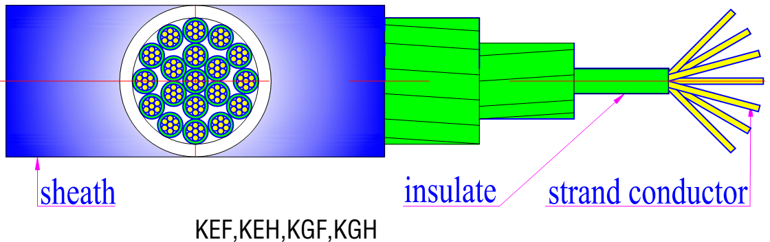
EPR (KEF) / silicon rubber (KGF) insulated, CR or CSM sheathed shipboard control cables with optional copper braid shield (P), for control, instrument, meter, monitoring and protection circuits; 2–37 cores, 0.5–6 mm².
View details →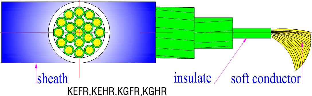
Soft-conductor (flexible) shipboard control cables for indoor mobile requirements; shielded (P) versions for EMC-sensitive circuits; 2–37 cores, 0.5–6 mm².
View details →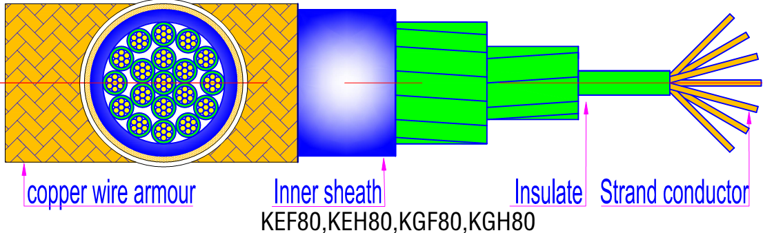
Armoured shipboard control cables — copper wire braid (80) or steel wire braid (90) armour, with optional PVC (82/92) or TPE (84/94) outer sheath; 2–37 cores, 0.5–6 mm².
View details →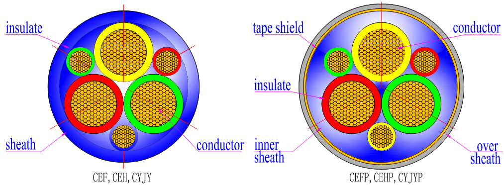
Ship convert (variable frequency) cables in 3 power cores + 3 protection cores construction, shielded (P) and flexible (R) variants, for power supply and inverter drive devices on vessels and offshore platforms.
View details →Request for Quotation
Send your drawing, specification or target standard — our engineers respond with a quotation, lead time and certification plan.